When I saw the video from Brady Dennis with the housing containing many flashing LEDs,
it was clear for me, to design a cache with LEDs too. But I didn’t want to limit the cache to cachers owning a smartphone. So the game is totally different from the one of Brady.
The target is, to investigate the right LED out of 14 (maybe that should be reduced to less ones) and to press a button, whenever that LED is on. No need to tell here more, because the video will show the game.
As ever: By clicking on the YouTube button, you can watch in 1080p quality…
After several looks to Brady’s video, I was wondering why his LEDs where changing their colors permanently. My sketch is containing a subroutine which is setting the three colors of the LED randomly whenever this subroutine is called. But this can’t be managed inside the sketch smoothly. So I asked him about the LEDs, he used:

While I bought 50 RGB LEDs with four pins (1 for ground, 3 for the different colors) he’s using so called „Rainbow LEDs“, which are changing their colors by themselves. These LEDs only need to be powered. They have an electronic circuit inside which makes the colors changing and flashing:
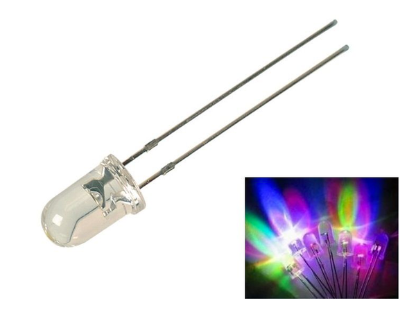
I found an offer at eBay. They’re costing much less. While my LEDs cost €1,50 each, I need to pay €3,20 for 10. There’re cheaper ones available, but they’re only changing the colors while these ones are also flashing. I just bought 10 times 10, so 100 will be in my local stock quite soon. I’m also thinking about to use them for the main display and not only for the housing.
Here’s a short video showing as they work (the Arduino is doeing nothing than providing the power…):
Testing will need to wait until we’re back from our vacation at the Red Sea in Egypt...
Update 5/24/2017
No, no, no, here’s a second video with the new Rainbow LEDs:
As ever: By clicking on the YouTube button, you can watch in 1080p quality…
The LEDs in the top row are all connected with the same analog pin of the Arduino (Mega), the bottom row to another. So I'm using only 2 pins for all this flashing LEDs. You can see in the video that sometimes both rows are on, off or only one is on.
Powered by USB one single analog pin is powering 10 LEDs. But that’s not the limit. I need to investigate, what the limit will be.
To keep the LEDs more healthy I’m setting the pin not to 1023 (max = 5 volts) but 800, which is roughly 3.9 volts only.
Update 6/23/2017
No, I wasn’t lazy! I’ve been on vacation at the Red Sea. But I also worked a little bit on the sketch. I think, the prototype is ready now. Have a look to the video below. As you can see, I’m able to power 20 flashing LEDs to one pin of the Arduino. In this case 40 flasing LEDs are used, powered by 2 analogue pins…
As ever: By clicking on the YouTube button, you can watch in 1080p quality…
Ideas on „version 2“:
- Amount of flasing LEDs: At this moment 2 x 20 LEDs are forseen for the housing, 20 of them powered by one single analogue pin. And I just switched them on at the beginning. Maybe there could be something more clever. The sketch is already programmed to switch 3 sets of flashing LEDs on or off.
- Amount of „game LEDs“: Inside this video I’m showing 14 LEDs being used. This amount can be easily decreased by a parameter inside the sketch. Some beta testing should show, if 14 are too much.
- Variable levels: (Usually „level“ is used as a matter of success. I don’t have a better word, but here the meaning is different: Level 1 means, playing without a hint, level 2 after the first hint, level 3 after the second hint and level 4 after the third (final) hint…)
In this version a timer is set to t (e.g. t=3 minutes). When the first time t is reached, hint 1 is shown. 5 (of the 14) LEDs will be on, meaning that one of this 5 is the right one. Now you’re in level 2… When t is reached the second time, 3 are shown (hint 2) and after t again, only the correct LED is shown. But during all levels, all LEDs will be used (in this case all 14). Maybe it would be a good idea, to use only 5 LEDs in level 2 (meaning after t passed the first time), 3 in level 3. But only 1 in level 4? This would mean, this forth level would be a „reaction testing level“ only. You have to press the key, when the LED is on and don’t when it’s off. Would be great to know what you’re thinking about! - Target: At this moment the target is set to 5. This means, you have to press 5 times the key, when the correct LED is on. Overtime you’re pressing the key wrongly, your level is decreased by 1, but never going below 0 (Zero). A beta testing should show, whether 5 is fine, or if the target should be higher. The target value is already programmed as a constant to be easily changed at the top of the sketch.
- ???: Any idea from your side… One thing is clear for me: I’ll integrate a servo to release the log instead of showing the code...
Update 11/14/2017
All the stuff is placed inside the housing and the cache is 95% ready to be placed. Have a look to the video here:
As ever: By clicking on the YouTube button, you can watch in 1080p quality…
The sketch is now available for download here...